Address
304 North Cardinal St.
Dorchester Center, MA 02124
Work Hours
Monday to Friday: 7AM - 7PM
Weekend: 10AM - 5PM
Address
304 North Cardinal St.
Dorchester Center, MA 02124
Work Hours
Monday to Friday: 7AM - 7PM
Weekend: 10AM - 5PM

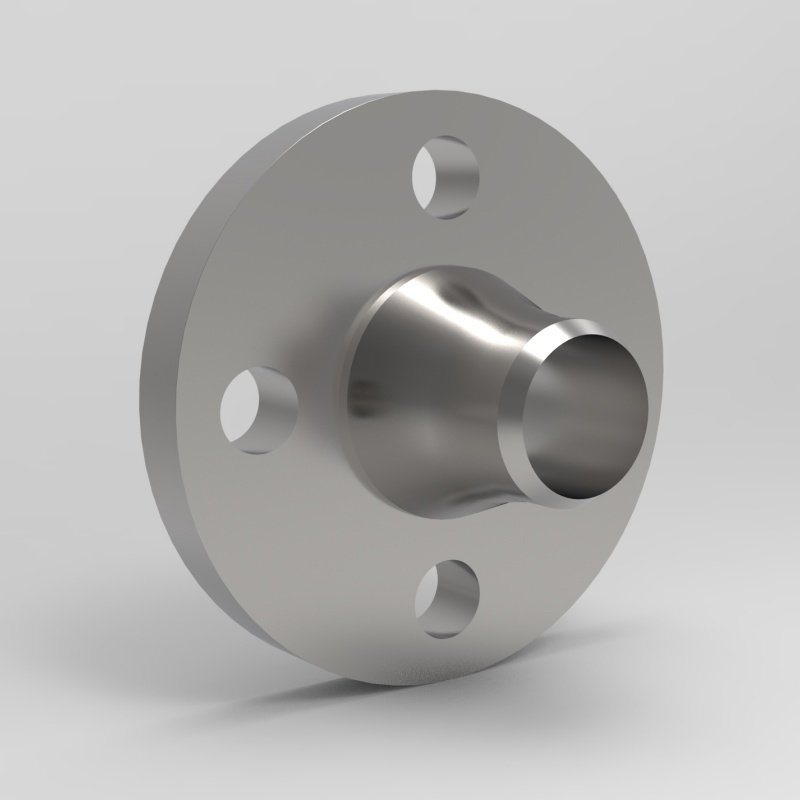
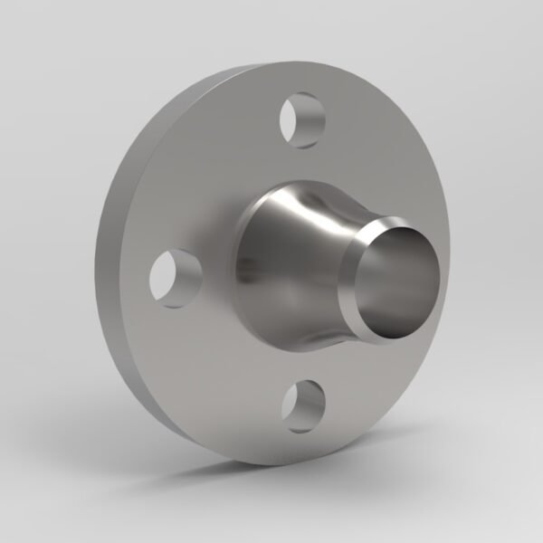
Nickel 200 and 201 forged pipe flanges to ASME SB-564 and B16.5, UNS N02200 / N02201. Weld neck, slip-on, socket weld and threaded. 3.1 MTC.
Nickel 200 and Nickel 201 forged pipe flanges are the pure-nickel connection for caustic soda, caustic potash, molten salts and the alkaline side of a chemical plant. Both grades are nominally 99 % nickel, and they differ only in carbon: UNS N02200 at 0.15 % maximum and UNS N02201 at 0.03 % maximum. That single difference decides the temperature range. Carbon in Nickel 200 graphitises at grain boundaries above about 315 °C, so Nickel 201 is the grade that has to be specified for anything above that temperature, and the two are interchangeable below it.
ASME B16.5 gives the flange its geometry, its class and its marking. ASME SB-564 covers UNS N02200 forgings; ASME B16.5 Table 1A lists the two grades separately, with UNS N02200 in material group 3.2 and UNS N02201 in material group 3.3. The rating tables are not the same, and the difference between them is large.
| Designation | Value |
|---|---|
| UNS numbers | N02200 (Nickel 200) and N02201 (Nickel 201) |
| Material specification | ASME SB-564 covers nickel alloy forgings and lists UNS N02200. ASME B16.5 Table 1A lists B 160 Gr. N02200 and B 162 Gr. N02200 for material group 3.2, and B 160 Gr. N02201 and B 162 Gr. N02201 for material group 3.3 |
| Dimensional standard | ASME B16.5 (NPS 1/2 to NPS 24); ASME B16.47 (NPS 26 to NPS 60) |
| Rating tables | ASME B16.5 Table 2-3.2 for UNS N02200 (group 3.2); ASME B16.5 Table 2-3.3 for UNS N02201 (group 3.3) |
| Material group | 3.2, nominal designation 99.0Ni (N02200); 3.3, nominal designation 99.0Ni–Low C (N02201) |
| Pressure class | Class 150, 300, 600, 900, 1500 and 2500 (Class 2500 to NPS 12 only) |
| Delivery condition | Annealed, per ASME SB-564 Table 2 |
| Marking | Per ASME B16.5 paragraph 4.2.3 and 4.2.8; nickel alloy forgings stamped in accordance with MSS SP-25 |
ASME B16.5 covers pressure-temperature ratings, materials, dimensions, tolerances, marking, testing and the method of designating openings for pipe flanges and flanged fittings in sizes NPS 1/2 through NPS 24, with rating class designations 150, 300, 400, 600, 900, 1500 and 2500, and Class 2500 applying to NPS 1/2 through NPS 12. For NPS 26 and larger ASME B16.47 takes over, covering welding neck and blind flanges in classes 75, 150, 300, 400, 600 and 900, in two dimensional series that are not interchangeable: Series A follows the former MSS SP-44 practice and Series B follows the former API 605 practice.
Two dimensional points decide whether a flange will actually mate. The first is the raised face height: ASME B16.5 paragraph 6.4.1 specifies that Classes 150 and 300 pipe flanges are regularly furnished with a 2 mm (0.06 in.) raised face and that Classes 400, 600, 900, 1500 and 2500 are regularly furnished with a 7 mm (0.25 in.) raised face, in each case in addition to the minimum flange thickness tf. A Class 150 flange therefore does not seat against a Class 600 flange without a gasket that tolerates the height difference. The second is the bore: ASME B16.5 note (7) to the dimension tables ties the bore to the inside diameter of B36.10M standard wall pipe, with Schedule 40 wall in NPS 10 and smaller, and paragraph 6.3.2 allows a raised face to be removed to convert a raised face flange to a flat face flange provided the required tf dimension is maintained.
Full dimension tables for Class 150 (Table F8), Class 300 (Table F11), Class 600 (Table F16) and Class 900 (Table F18) are published separately on this site in ASME B16.5 flange dimensions: Class 150, 300, 600 and 900, and the boundary between the two flange standards is covered in ASME B16.5 or B16.47: which flange standard applies at what size.
The flange types supplied for these two grades are welding neck, slip-on, socket weld, threaded, lap joint and blind, with socket welding flanges produced to NPS 3 and smaller only. Welding neck is the usual selection for a caustic line, and the reason is thermal rather than corrosion: a caustic evaporator is a large thin-walled vessel whose flange sees movement that a steel flange would not tolerate, and the 40 % elongation available in the annealed condition lets the joint take up that movement rather than cracking the weld. Blind flanges are used to isolate a section for vessel entry, and on a high-temperature caustic service the Nickel 201 grade is the one that has to be used, because the graphitisation risk in the flange is the same risk as in the vessel wall and the flange must not be the weak link in it.
| Element | Composition, % (max unless stated) |
|---|---|
| Nickel | 99.0 min, determined by difference (N02200); 99.0 min for the low-carbon grade N02201 |
| Carbon | 0.15 (N02200) |
| Manganese | 0.35 |
| Silicon | 0.35 |
| Copper | 0.25 |
| Iron | 0.40 |
| Sulfur | 0.01 |
| Chromium, molybdenum, niobium, titanium | not required by ASME SB-564 Table 1 |
Source: ASME SB-564 Table 1, chemical requirements for nickel alloy UNS N02200, and ASME B16.5 Table 1A for the identification of the two grades. The chemistry above is the ASME SB-564 Table 1 column for UNS N02200. ASME SB-564 scope covers UNS N02200; ASME SB-366 Table 2 lists UNS N02201 with B 160 as the raw material route, and ASME B16.5 Table 1A lists B 160 Gr. N02201 and B 162 Gr. N02201 for group 3.3. The full N02201 chemistry table in ASME SB-564 is not reproduced here, so the certificate for a Nickel 201 flange should be checked against the applicable material specification on the order. There is no chromium in either grade, and the corrosion resistance comes from nickel itself rather than from a passive chromium oxide film, which is exactly why these flanges handle caustic and molten salts that stainless steel cannot touch.
| Property | Requirement |
|---|---|
| Tensile strength, min | 55 ksi (380 MPa) |
| Yield strength, 0.2 % offset, min | 15 ksi (105 MPa) |
| Elongation in 2 in. or 50 mm, min | 40 % |
| Condition | Annealed |
Source: ASME SB-564 Table 2, mechanical property requirements for nickel alloy UNS N02200, annealed. ASME B16.5 notes (1) and (2) to Tables 2-3.2 and 2-3.3 require annealed material only, and state that the chemical composition, mechanical properties, heat treating requirements and grain size requirements shall conform to the applicable ASTM specification while the manufacturing procedures, tolerances, tests, certification and markings shall be in accordance with ASTM B 564. For the N02201 condition, the mechanical properties of the applicable material specification have to be confirmed at order stage: TBC, and we will state the figure against the specification you nominate.
| Temperature, °C | Class 150 | Class 300 | Class 400 | Class 600 | Class 900 | Class 1500 | Class 2500 |
|---|---|---|---|---|---|---|---|
| −29 to 38 | 12.7 | 33.1 | 44.1 | 66.2 | 99.3 | 165.5 | 275.8 |
| 50 | 12.7 | 33.1 | 44.1 | 66.2 | 99.3 | 165.5 | 275.8 |
| 100 | 12.7 | 33.1 | 44.1 | 66.2 | 99.3 | 165.5 | 275.8 |
| 150 | 12.7 | 33.1 | 44.1 | 66.2 | 99.3 | 165.5 | 275.8 |
| 200 | 12.7 | 33.1 | 44.1 | 66.2 | 99.3 | 165.5 | 275.8 |
| 250 | 12.1 | 31.6 | 42.1 | 63.2 | 94.8 | 158.0 | 263.4 |
| 300 | 10.2 | 29.2 | 39.0 | 58.5 | 87.7 | 146.2 | 243.7 |
UNS N02201, material group 3.3 — ASME B16.5 Table 2-3.3.
| Temperature, °C | Class 150 | Class 300 | Class 400 | Class 600 | Class 900 | Class 1500 | Class 2500 |
|---|---|---|---|---|---|---|---|
| −29 to 38 | 6.3 | 16.5 | 22.1 | 33.1 | 49.6 | 82.7 | 137.9 |
| 50 | 6.3 | 16.4 | 21.9 | 32.8 | 49.2 | 82.0 | 136.7 |
| 100 | 6.1 | 15.8 | 21.1 | 31.7 | 47.5 | 79.2 | 132.0 |
| 150 | 6.0 | 15.6 | 20.7 | 31.1 | 46.7 | 77.8 | 129.6 |
| 200 | 6.0 | 15.6 | 20.7 | 31.1 | 46.7 | 77.8 | 129.6 |
| 250 | 6.0 | 15.6 | 20.7 | 31.1 | 46.7 | 77.8 | 129.6 |
| 300 | 6.0 | 15.6 | 20.7 | 31.1 | 46.7 | 77.8 | 129.6 |
Sources: ASME B16.5 Table 2-3.2 for group 3.2 materials (UNS N02200) and Table 2-3.3 for group 3.3 materials (UNS N02201), expressed in bar. Intermediate temperatures may be interpolated linearly between tabulated values. Only annealed material may be used for these ratings.
The flanges are forged and supplied annealed, then machined, drilled and pickled. ASME SB-564 Table 2 gives the annealed condition and ASME B16.5 note (1) to both rating tables allows nothing else for the pressure rating. Heat treatment may be performed before machining.
The heat treatment condition of the material is what decides which of the two grades to use, and this is a welding and operating temperature question rather than a purchase question. Carbon in Nickel 200 precipitates as graphite at grain boundaries above roughly 315 °C, producing intergranular embrittlement and cracking in the grain-boundary network. Nickel 201 with its much lower carbon does not graphitise and is the grade for caustic evaporators and concentrators above that temperature, for molten salt service, for high temperature reducing atmospheres in heat treatment furnaces and for dry halogen gas handling above 315 °C. Below that temperature the two grades are effectively interchangeable and the choice comes down to the specification and the certificate.
Welding Nickel 200 or 201 requires a qualified procedure to ASME Section IX with filler metal matching the grade, and the heat input has to be controlled so that the weld metal does not pick up carbon or sulphur contamination. Because the alloys have no chromium, there is no chromium carbide sensitisation mechanism to manage; the vulnerability is graphitisation, and it is avoided by grade selection and by keeping the service below the graphitisation temperature.
Supplementary testing on these grades is supplied when it is named on the order rather than assumed: hardness testing, charpy impact testing, ultrasonic or eddy current examination, positive material identification and liquid penetrant examination. Because these alloys are nominally pure nickel, positive material identification is worth more here than on a chromium-bearing alloy: there is no chromium passivation to fall back on, so a mixed grade in a caustic line is not a cosmetic problem. Where the flange is to be used above 315 °C, the certification route should be agreed at enquiry stage so that the UNS number on the certificate matches the grade in the rating table being applied to the design.
Each flange is marked with the material grade and specification, the nominal
size, the pressure class and the heat number. The rating designation number
corresponding to the pressure rating class is applied to the flange in accordance
with ASME B16.5. Where the flange is made from a material that meets more than one
specification or grade, the marking procedure of ASME B16.5 for multiple material
marking is followed. Nickel alloy forgings are stamped in accordance with MSS SP-25
in a position that does not impair the usefulness of the forging. B16.5 also
permits the manufacturer to supplement the mandatory material indications with a
trade designation, provided confusion of symbols is avoided.
Flanges are supplied in the annealed condition, pickled, with a machined sealing
face. Each flange carries the grade, the governing material specification, the
dimensional standard, the nominal size, the pressure class and the heat number,
linked to the EN 10204 certificate issued with the shipment. Export packing is by
wooden crate, steel pallet or case, with plastic end caps and, where required, VCI
protection inside the case. Flange facings are protected individually so that the
sealing surface is not marked in transit. Delivery schedule, quantity, minimum
order quantity and price are confirmed only against a specific enquiry.
Nickel 200 and 201 flanges are specified in caustic soda and caustic potash evaporators, crystallisers and heat exchangers, in the caustic side of pulp and paper bleaching, in chlor-alkali plants handling caustic liquor and brine, in the production of nickel salts and in electroplating chemistry, in molten salt heat treatment furnaces, in high temperature reducing atmospheres, in dry halogen gas handling, and in pharmaceutical and food processing where the alloy is used for its inertness towards alkalis and food acids. Below 315 °C they also appear in general seawater and salt service, and in the alkalis handling side of a refinery.
The two grades are not interchangeable for pressure, only for temperature. ASME B16.5 Table 1A gives UNS N02200 its own material group 3.2 and UNS N02201 its own group 3.3, with separate rating tables. At ambient the Class 150 rating for group 3.2 is 12.7 bar, while group 3.3 rates at 6.3 bar — half the value. That is not a typo in the tables and it is not a small difference: the Class 300 rating falls from 33.1 bar to 16.5 bar and Class 600 from 66.2 bar to 33.1 bar. So a Nickel 201 flange on the same class and size is materially the weaker component than a Nickel 200 flange, and the low-carbon grade has to be sized against its own table. The low carbon buys the resistance to graphitisation above 315 °C, and it is paid for in pressure capacity.
Why the strength is so low and why that is the right answer. ASME SB-564 Table 2 gives Nickel 200 a 55 ksi (380 MPa) tensile and 15 ksi (105 MPa) yield with 40 % elongation in the annealed condition. For a pressure part that looks like a weak alloy, and against a 100 ksi Class 150 stainless steel it is. It is also the correct number, because these flanges are not usually loaded by internal pressure in the way a process line is. The driving stresses in a caustic evaporator are thermal gradients, vibration and differential expansion across a large, thin-walled vessel, and the failure mode the metallurgy is bought for is corrosion, not yielding. The 40 % elongation in the annealed condition is a genuine asset in that context, because the flange has to take up movement without cracking the weld or the parent metal. The right way to specify these flanges is by temperature, corrosion environment and dimensional standard, not by trying to make them compete with a stainless steel on pressure.
The carbon threshold is the design decision, and it belongs in the purchase order. Graphitisation of Nickel 200 begins above about 315 °C and the consequence is intergranular cracking and eventual embrittlement of the flange, in the same way as the parent metal in the vessel it is welded to. Nickel 201 eliminates it, which is why ASME B16.5 puts the two grades in separate groups rather than treating them as one alloy with a preference. Note also that the material route is different for the two: ASME SB-564 lists UNS N02200, ASME SB-366 Table 2 lists UNS N02201 with B 160 as the raw material, and ASME B16.5 Table 1A lists B 160 Gr. N02201 and B 162 Gr. N02201 for group 3.3. Because the two grades sit in different groups with different rating tables and different raw material routes, the UNS number has to be written on the order. Writing “Nickel 200/201” on the purchase order is the one form of specification that guarantees a mismatch between the certificate and the rating.
Both are nominally 99 % nickel. UNS N02200 has a 0.15 % carbon maximum and UNS N02201 has 0.03 % maximum. Nickel 200 graphitises at grain boundaries above about 315 °C, so Nickel 201 is the grade for caustic evaporators, molten salts and high temperature reducing atmospheres above that point.
No. ASME B16.5 puts UNS N02200 in material group 3.2 with rating table 2-3.2 and UNS N02201 in material group 3.3 with rating table 2-3.3. At Class 150 ambient the ratings are 12.7 bar and 6.3 bar respectively, so the low-carbon grade has to be sized against its own table.
ASME SB-564 covers nickel alloy forgings and lists UNS N02200. ASME SB-366 Table 2 lists UNS N02201 with B 160 as the raw material route, and ASME B16.5 Table 1A lists B 160 Gr. N02201 and B 162 Gr. N02201 for material group 3.3. The UNS number and the governing material specification should both be on the order.
ASME SB-564 Table 2 gives Nickel 200 a 55 ksi (380 MPa) tensile and 15 ksi (105 MPa) yield in the annealed condition. These flanges are normally driven by thermal and corrosion stresses rather than by internal pressure, and the 40 % elongation in the annealed condition is what allows the flange to take up movement without cracking.
Welding neck, slip-on, socket weld, threaded, lap joint and blind, per ASME B16.5, with socket welding flanges to NPS 3 only. Welding neck is normally used where the flange is welded into the line.
Annealed, per ASME SB-564 Table 2, and ASME B16.5 notes (1) and (2) to Tables 2-3.2 and 2-3.3 allow annealed material only for the pressure rating, with the composition, mechanical properties and heat treating requirements taken from the applicable ASTM specification.