Address
304 North Cardinal St.
Dorchester Center, MA 02124
Work Hours
Monday to Friday: 7AM - 7PM
Weekend: 10AM - 5PM
Address
304 North Cardinal St.
Dorchester Center, MA 02124
Work Hours
Monday to Friday: 7AM - 7PM
Weekend: 10AM - 5PM

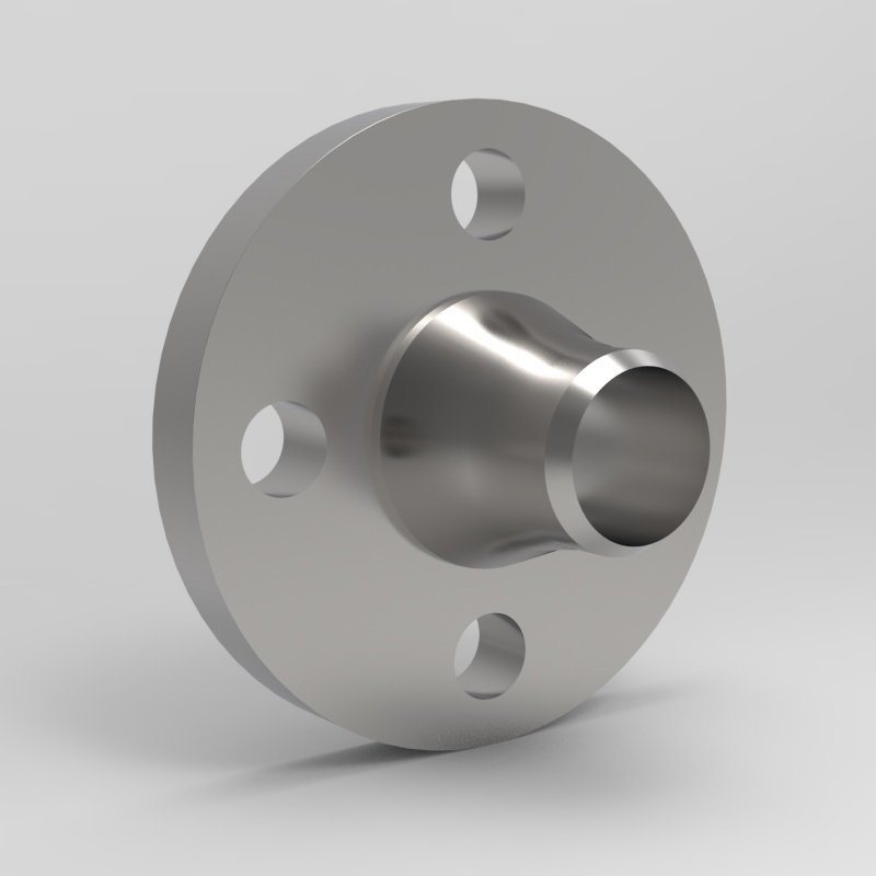
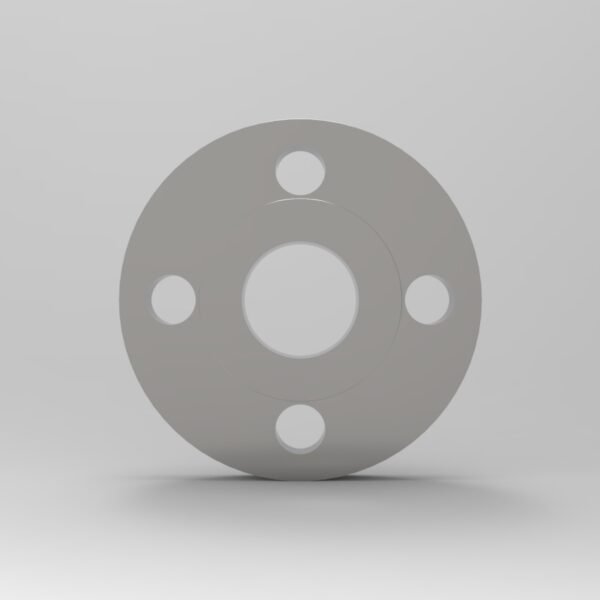
Stainless steel 316 and 316L forged pipe flanges to ASME SA-182 and B16.5, UNS S31600 / S31603. Weld neck, slip-on, socket weld and blind.
Stainless steel 316 and 316L forged pipe flanges are the standard corrosion-resistant flange for the overwhelming majority of chemical, pharmaceutical, food and general process piping, and specifying them properly matters more than specifying them correctly. The 2 % to 3 % molybdenum in 316 is what lifts it from the 304 general-purpose grade and gives it resistance to chloride pitting, and the carbon control differentiates the two: UNS S31600 at 0.08 % maximum and the low-carbon UNS S31603 at 0.030 % maximum. For a forged flange that is welded into the line, the low-carbon grade is usually the right choice, because the chromium carbide precipitation that sensitises the heat-affected zone of a welded 316 joint does not occur in 316L.
ASME SA-182 covers the forging and ASME B16.5 covers the dimensions, the pressure classes and the marking. Write both. Note that the two grades sit in different B16.5 material groups with different rating tables, so the grade named on the order changes the pressure the flange is allowed to carry.
| Designation | Value |
|---|---|
| UNS numbers | S31600 (316) and S31603 (316L) |
| Material specification | ASME SA-182 (forged or rolled alloy and stainless steel pipe flanges, forged fittings and valves). ASME B16.5 Table 1A lists A 182 Gr. F 316 in material group 2.2 and A 182 Gr. F 316L in material group 2.3 |
| Dimensional standard | ASME B16.5 (NPS 1/2 to NPS 24); ASME B16.47 (NPS 26 to NPS 60) |
| Rating tables | ASME B16.5 Table 2-2.2 for A 182 Gr. F 316 (group 2.2); ASME B16.5 Table 2-2.3 for A 182 Gr. F 316L (group 2.3) |
| Material group | 2.2, nominal designation 16Cr–12Ni–2Mo (F 316); 2.3, same nominal designation (F 316L) |
| Pressure class | Class 150, 300, 600, 900, 1500 and 2500 (Class 2500 to NPS 12 only) |
| Delivery condition | Solution treated and quenched, per ASME SA-182 Table 1 |
| Marking | Per ASME B16.5 paragraph 4.2.3 and 4.2.8 |
ASME B16.5 covers pressure-temperature ratings, materials, dimensions, tolerances, marking, testing and the method of designating openings for pipe flanges and flanged fittings in sizes NPS 1/2 through NPS 24, with rating class designations 150, 300, 400, 600, 900, 1500 and 2500, and Class 2500 applying to NPS 1/2 through NPS 12. For NPS 26 and larger ASME B16.47 takes over, covering welding neck and blind flanges in classes 75, 150, 300, 400, 600 and 900, in two dimensional series that are not interchangeable: Series A follows the former MSS SP-44 practice and Series B follows the former API 605 practice.
Two dimensional points decide whether a flange will actually mate. The first is the raised face height: ASME B16.5 paragraph 6.4.1 specifies that Classes 150 and 300 pipe flanges are regularly furnished with a 2 mm (0.06 in.) raised face and that Classes 400, 600, 900, 1500 and 2500 are regularly furnished with a 7 mm (0.25 in.) raised face, in each case in addition to the minimum flange thickness tf. A Class 150 flange therefore does not seat against a Class 600 flange without a gasket that tolerates the height difference. The second is the bore: ASME B16.5 note (7) to the dimension tables ties the bore to the inside diameter of B36.10M standard wall pipe, with Schedule 40 wall in NPS 10 and smaller, and paragraph 6.3.2 allows a raised face to be removed to convert a raised face flange to a flat face flange provided the required tf dimension is maintained.
Full dimension tables for Class 150 (Table F8), Class 300 (Table F11), Class 600 (Table F16) and Class 900 (Table F18) are published separately on this site in ASME B16.5 flange dimensions: Class 150, 300, 600 and 900, and the boundary between the two flange standards is covered in ASME B16.5 or B16.47: which flange standard applies at what size.
The flange types supplied are welding neck, slip-on, socket weld, threaded, lap joint and blind, with socket welding flanges produced to NPS 3 and smaller only. Welding neck is the normal choice for welded process piping, and it is the only sensible choice where the flange is welded into the line, because the heat-affected zone at the flange-to-pipe weld is a critical part of the corrosion design and it is far easier to qualify a single procedure at one joint than a slip-on joint that has to be welded twice, once at each end of the pipe stub. A slip-on or threaded flange is used where the connection has to be opened for inspection or cleaning without cutting the pipe, and a blind flange is used to isolate a section or a vessel nozzle.
| Element | Composition, % (max unless stated) |
|---|---|
| Chromium | 16.0 – 18.0 (both grades) |
| Nickel | 10.0 – 14.0 (F 316); 10.0 – 15.0 (F 316L) |
| Molybdenum | 2.00 – 3.00 (both grades) |
| Carbon | 0.08 (F 316); 0.030 (F 316L) |
| Manganese | 2.00 |
| Phosphorus | 0.045 |
| Sulfur | 0.030 |
| Silicon | 1.00 |
| Nitrogen | 0.10 (F 316 and F 316L) |
| Niobium, titanium | not required by ASME SA-182 Table 2 |
Source: ASME SA-182 Table 2, chemical requirements for grade symbols F 316 (UNS S31600) and F 316L (UNS S31603). The 2 % to 3 % molybdenum is the whole difference from 304 and the reason 316 is specified for chloride-bearing process service. The lower carbon of F 316L is what makes it the preferred grade for a welded flange, because the chromium carbide precipitation that causes sensitisation in the heat-affected zone of a welded 316 joint does not occur. Note that the nickel range for F 316L in ASME SA-182 is 10.0 % to 15.0 %, wider at the top than the 10.0 % to 14.0 % of F 316, so a certificate quoting the wider range is not automatically a different material.
| Property | Requirement |
|---|---|
| Tensile strength, min | 75 ksi (515 MPa) for F 316; 70 ksi (485 MPa) for F 316L. For sections over 5 in. (130 mm) in thickness the minimum tensile strength is 70 ksi (485 MPa) for F 316 and 65 ksi (450 MPa) for F 316L |
| Yield strength, 0.2 % offset, min | 30 ksi (205 MPa) for F 316; 25 ksi (170 MPa) for F 316L |
| Elongation in 2 in. or 50 mm, min | 30 % for both grades |
| Reduction of area, min | 50 % for both grades |
| Hardness | not specified in ASME SA-182 Table 3 for these grades |
| Condition | Solution treated and quenched |
Source: ASME SA-182 Table 3, tensile and hardness requirements. The yield strength is determined by the 0.2 % offset method. ASME SA-182 Table 1 gives the heat treatment: solution treat and quench at 1900 °F (1040 °C) minimum, quenched in liquid, with the quench cooled below 500 °F (260 °C). ASME SA-182 paragraph 11.1 states that corrosion testing is not required by the specification, but paragraph 11.2 requires austenitic grades to be capable of meeting the intergranular corrosion test requirements of Supplementary Requirement S4 when that supplementary requirement is specified on the order.
| Temperature, °C | Class 150 | Class 300 | Class 400 | Class 600 | Class 900 | Class 1500 | Class 2500 |
|---|---|---|---|---|---|---|---|
| −29 to 38 | 19.0 | 49.6 | 66.2 | 99.3 | 148.9 | 248.2 | 413.7 |
| 50 | 18.4 | 48.1 | 64.2 | 96.2 | 144.3 | 240.6 | 400.9 |
| 100 | 16.2 | 42.2 | 56.3 | 84.4 | 126.6 | 211.0 | 351.6 |
| 150 | 14.8 | 38.5 | 51.3 | 77.0 | 115.5 | 192.5 | 320.8 |
| 200 | 13.7 | 35.7 | 47.6 | 71.3 | 107.0 | 178.3 | 297.2 |
| 250 | 12.1 | 33.4 | 44.5 | 66.8 | 100.1 | 166.9 | 278.1 |
| 300 | 10.2 | 31.6 | 42.2 | 63.2 | 94.9 | 158.1 | 263.5 |
UNS S31603 (F 316L), material group 2.3 — ASME B16.5 Table 2-2.3.
| Temperature, °C | Class 150 | Class 300 | Class 400 | Class 600 | Class 900 | Class 1500 | Class 2500 |
|---|---|---|---|---|---|---|---|
| −29 to 38 | 15.9 | 41.4 | 55.2 | 82.7 | 124.1 | 206.8 | 344.7 |
| 50 | 15.3 | 40.0 | 53.4 | 80.0 | 120.1 | 200.1 | 333.5 |
| 100 | 13.3 | 34.8 | 46.4 | 69.6 | 104.4 | 173.9 | 289.9 |
| 150 | 12.0 | 31.4 | 41.9 | 62.8 | 94.2 | 157.0 | 261.6 |
| 200 | 11.2 | 29.2 | 38.9 | 58.3 | 87.5 | 145.8 | 243.0 |
| 250 | 10.5 | 27.5 | 36.6 | 54.9 | 82.4 | 137.3 | 228.9 |
| 300 | 10.0 | 26.1 | 34.8 | 52.1 | 78.2 | 130.3 | 217.2 |
Sources: ASME B16.5 Table 2-2.2 for group 2.2 materials (A 182 Gr. F 316) and Table 2-2.3 for group 2.3 materials (A 182 Gr. F 316L), expressed in bar. Intermediate temperatures may be interpolated linearly between tabulated values. The lower values for F 316L reflect its lower minimum yield strength, not a difference in the material class of the joint.
316 and 316L flanges are forged from bar or billet, solution treated and quenched, then machined, drilled and pickled. ASME SA-182 Table 1 requires solution treat and quench at 1900 °F (1040 °C) minimum with liquid quenching and the quench cooled below 500 °F (260 °C). The quench rate through the intermediate range is what preserves the austenitic structure, and it is the reason the cooling medium temperature is controlled rather than left open.
Weld repairs are permitted under ASME SA-182 clause 15, with the welding procedure and welders qualified to Section IX of the ASME Boiler and Pressure Vessel Code and the weld metal deposited using the electrodes specified in Table 4. For a 316L flange the filler should be the low-carbon matching grade, and the heat input has to be controlled so that the heat-affected zone does not pick up enough carbon to precipitate chromium carbide. That is the reason F 316L is normally specified for a flange that is welded into the line, while F 316 remains the correct choice where the flange is not welded, where higher strength is wanted, or where the service is at low temperature.
ASME SA-182 paragraph 14.1 requires the forgings and finished parts to conform to the requirements of Specification A961/A961M for surface finish, appearance and corrosion protection, and paragraph 14.2 requires them to be free of scale and machining burrs that might hinder fit-up, with machined surfaces not exceeding 250 AA arithmetic average roughness. The sealing face is machined to the finish the gasket requires, which for a spiral wound gasket in 316L service is normally a better finish than the general 250 AA figure for the rest of the flange.
Supplementary testing on these grades is supplied when it is named on the order rather than assumed: hardness testing, charpy impact testing, intergranular corrosion testing to ASTM A262, ultrasonic or eddy current examination, positive material identification and liquid penetrant examination. ASME SA-182 paragraph 11.2 requires austenitic grades to be capable of meeting the intergranular corrosion test requirements of Supplementary Requirement S4, and that supplementary requirement is the usual route by which an intergranular corrosion test is specified on a 316L order. For cryogenic service the impact testing of ASME SA-182 Section 9 and the lower toughness of the austenitic grades at low temperature have to be considered separately from the room-temperature properties.
Each flange is marked with the material grade and specification, the nominal
size, the pressure class and the heat number. The rating designation number
corresponding to the pressure rating class is applied to the flange in accordance
with ASME B16.5. Where the flange is made from a material that meets more than one
specification or grade, the marking procedure of ASME B16.5 for multiple material
marking is followed. Nickel alloy forgings are stamped in accordance with MSS SP-25
in a position that does not impair the usefulness of the forging. B16.5 also
permits the manufacturer to supplement the mandatory material indications with a
trade designation, provided confusion of symbols is avoided.
Flanges are supplied in the annealed condition, pickled, with a machined sealing
face. Each flange carries the grade, the governing material specification, the
dimensional standard, the nominal size, the pressure class and the heat number,
linked to the EN 10204 certificate issued with the shipment. Export packing is by
wooden crate, steel pallet or case, with plastic end caps and, where required, VCI
protection inside the case. Flange facings are protected individually so that the
sealing surface is not marked in transit. Delivery schedule, quantity, minimum
order quantity and price are confirmed only against a specific enquiry.
Stainless steel 316 and 316L flanges are used across chemical processing, pharmaceutical and biopharmaceutical plant, food and beverage processing, dairy, brewing and pulp and paper, oil and gas production equipment, potable water and wastewater treatment, marine and coastal installations, heat exchanger and condenser headers, and general corrosion-resistant piping where chlorides are present at moderate temperature. The 316L grade dominates in welded process piping because of its resistance to sensitisation, while F 316 is used where higher strength or cryogenic service is required and where the flange is not welded into the line.
The grade named on the order changes the rating table. ASME B16.5 Table 1A places A 182 Gr. F 316 in material group 2.2 and A 182 Gr. F 316L in material group 2.3, and those two groups have separate pressure-temperature tables. At ambient the Class 150 rating is 19.0 bar for F 316 and 15.9 bar for F 316L; at Class 300 it is 49.6 bar against 41.4 bar. This follows directly from the minimum yield strengths in ASME SA-182 Table 3, 30 ksi (205 MPa) for F 316 and 25 ksi (170 MPa) for F 316L. It is not a classification of quality and the low-carbon grade is not the weaker material in service; it simply carries a lower tabulated allowable because the specification allows less of it. The practical consequence is that a joint where the flange is F 316L and the pipe is rated for the F 316 allowable has to be checked against the F 316L table.
Why the low-carbon grade is the right default for a welded flange. The failure mode for a welded austenitic stainless part is not the weld metal, it is the heat-affected zone. During cooling, chromium combines with carbon at the grain boundaries and precipitates as chromium carbide, leaving the immediately adjacent metal depleted in chromium and therefore without its protective film. That zone then corrodes intergranularly, and in a chloride service the attack is rapid. F 316L at 0.030 % carbon maximum suppresses the carbide formation, so the heat-affected zone of a properly welded F 316L flange retains its corrosion resistance and needs no post-weld heat treatment to restore it. F 316 at 0.08 % carbon does not have that protection, which is why ASME SA-182 paragraph 11.2 requires austenitic grades to be capable of meeting the intergranular corrosion test of Supplementary Requirement S4 when that requirement is invoked on the order, and why the grade choice for a welded flange is a corrosion decision rather than a cost one.
Matching the flange grade to the pipe grade. A flange welded to a pipe has to match that pipe, both in grade and in the fact that it is welded. The common specification error is a 316L pipe with an F 316 flange, which puts the sensitised heat-affected zone of the higher-carbon grade right at the joint, and it is worse than a uniform error because it puts the weakest element exactly where the crevice geometry and the weld are. When the order calls for 316L piping, the flange should be F 316L, and the certification should be read against the same grade on both items. Where the service is cryogenic, the ASTM A182 scope note on the lower impact toughness of the austenitic grades at low temperature has to be considered separately from the room temperature properties quoted here.
For a flange welded into the line, F 316L. Its 0.030 % carbon maximum suppresses chromium carbide precipitation in the heat-affected zone, so the welded joint keeps its corrosion resistance without post-weld heat treatment. F 316 remains appropriate where the flange is not welded, where higher strength is needed or for cryogenic service.
ASME B16.5 puts them in different material groups, 2.2 and 2.3, with separate rating tables. The difference follows from the minimum yield strengths in ASME SA-182 Table 3, 30 ksi for F 316 and 25 ksi for F 316L. At Class 150 ambient the ratings are 19.0 bar and 15.9 bar.
Solution treat and quench at 1900 °F (1040 °C) minimum, quenched in liquid with the quench cooled below 500 °F (260 °C), per ASME SA-182 Table 1. Controlling the cooling rate through the intermediate range is what preserves the austenitic structure.
ASME SA-182 paragraph 11.1 states that corrosion testing is not required by the specification. Paragraph 11.2 requires austenitic grades to be capable of meeting the intergranular corrosion test requirements of Supplementary Requirement S4, which is invoked on the order when an intergranular corrosion test is required.
Welding neck, slip-on, socket weld, threaded, lap joint and blind per ASME B16.5, with socket welding flanges to NPS 3 only. Welding neck is normally used for butt-welded process piping.
ASME SA-182 paragraph 14.1 requires conformance to Specification A961/A961M, and paragraph 14.2 requires the parts to be free of scale and machining burrs that might hinder fit-up, with machined surfaces not exceeding 250 AA roughness. The sealing face is machined to the finish the gasket requires.